Network segmentation is a great way to compartmentalize the various networks you need to run in your environment. This provides many benefits from both a management and security perspective. When segmenting your networks, one of the things that you have to consider and take care of is IP addressing. Dynamic Host Configuration Protocol (DHCP) is an age-old standard that has been used in the enterprise for handing out IP addresses to clients on the network. DHCP requires its own broadcast domain, which in turn requires VLANs. Many organizations are using Windows Server for DHCP on their networks. In this post, we will take a look at Windows Server DHCP VLAN configuration. These steps work for Windows Server 2012, 2016, 2019, and Windows Server 2022.wind
Why are VLANs needed for DHCP?
When a client is provisioned on a network segment and is set up to have IP addressing configured automatically using DHCP, the client makes broadcast queries on the network segment to notify the DHCP server configured that it needs an IP address. The DHCP server responds with the appropriate IP address for the network segment and the additional configuration for network connectivity on the segment.
VLANs (Virtual Local Area Networks) allow taking a physical network switch and logically segmenting the physical network environment into multiple network segments. This makes much more efficient use of network hardware since additional segments do not require additional physical network switches. By introducing VLANs, you can provision multiple network segments on the same switch.
When you spin up a new network segment IP address range, you want to pair this with a new VLAN or logical network segment. VLANs control broadcast ranges. Within each VLAN, clients can initiate the broadcast for a network IP address from a DHCP server. There are many different ways to have a Windows Server participate in a VLAN network segment. Before we look at the specifics related to DHCP VLAN configuration, let’s take a look at the multiple options for connecting the Windows host into a VLAN-backed network.
Connecting Windows Server to Multiple VLANs
There are many different ways to connect Windows Server to multiple VLANs. This includes the following:
- Additional network interfaces Untagged for VLAN traffic
- A single network interface with Tagged VLAN frames
- Routed Layer 3 connectivity to VLAN-backed subnets
Additional network interfaces Untagged for VLAN traffic
With VLANs, you hear two different terms tossed out there related to the VLAN you are working with – untagged, and tagged. When you talk about untagged frames, this means the Windows host is not tagging the Ethernet frames originating from the host with VLAN information. Instead, it is relying on the upstream switch it is plumbed into to handle that configuration.
So, essentially, the Windows Server is unaware of the VLAN and doesn’t care. It simply relies on its physical uplink to do any VLAN tagging for it to communicate appropriately. However, this means that if you want to have a Windows Server to be a part of multiple VLANs, it means you need a physical uplink for each separate VLAN, since it is relying on the switch to tag the traffic appropriately for a specific VLAN.
As shown below on a Windows Server 2019 server, you can specify the Bindings for the Windows DHCP Server so that it knows which interfaces to “listen” for DHCP on.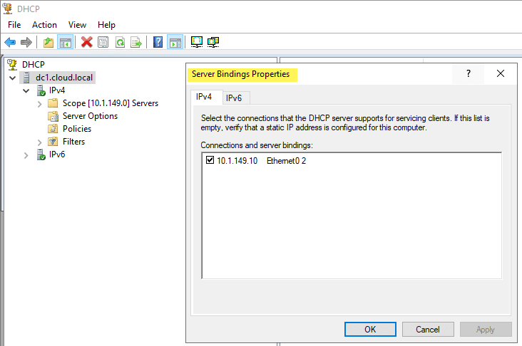 Configuring dhcp interface bindings for windows server 2012 and higher dhcp
A single network interface with Tagged VLAN frames
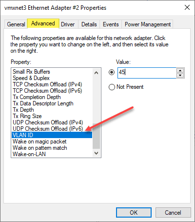
While there may be reasons that you use multiple physical uplinks with untagged frames for communicating with different VLANs, a more efficient approach is to use Tagged VLAN frames on a single network connection. When you use tagged frames, the Windows Server tags the frames appropriately for each VLAN it is associated with. The ability to Tag frames generally needs vendor-specific driver sets to be loaded, such as the Intel Pro Set drivers using Intel-based cards.
Routed Layer 3 connectivity to VLAN-backed subnets
The third option is simply relying on routing to take care of connectivity to the VLAN-backed subnets they need to communicate with. This technically does not connect the Windows Server into the VLAN as that would mean it would have the ability to be in the broadcast domain which is a Layer 2 VLAN construct. Instead, you are relying on Layer 3 connectivity to IP addresses. For many type of communication, including Windows Server 2012 DHCP VLAN configuration, this is all that is needed.
Windows Server DHCP VLAN Configuration
You can use all three of the methods above for Windows Server 2012, 2016, 2019, and Windows Server 2022 DHCP VLAN configuration. You can add multiple network adapters to each VLAN and have each scope listen on that specific network interface for DHCP requests. You can also use the tagging method listed above that allows adding multiple VLANs to a single network interface which allows keeping a single network adapter and connecting that physical network uplink to multiple VLANs.
You might assume the third option, since it is not connecting the uplink to the physical broadcast domain, would not be able to answer the broadcast DHCP request from the client on a specific VLAN. However, even though the DHCP server is not on the same broadcast domain/VLAN, there are really only two pieces of information the DHCP servers need to know to allocate an IP address on a particular subnet. This includes:
- Source subnet of the client
- MAC address of the client
You will note that the Windows Server DHCP server being a part of the VLAN is not a requirement for a successful DHCP request being made to the Windows Server. The third option is typically the option that I steer towards unless there are requirements for multiple physical uplinks for compliance or other security-based reasons. So, how does the Windows DHCP Server respond to a DHCP broadcast request if it is not on the same VLAN to take part in the broadcast traffic?
IP Helper Address, DHCP Relay, DHCP Proxy Address
This is made possible by the IP Helper Address which is sometimes referred to as DHCP Relay, or DHCP proxy address. Using an IP helper address, DHCP Relay, or DHCP proxy address allows the special DHCP broadcast messages to be forwarded from VLAN they originated from and forwarded to the DHCP server. This role is typically handled by a firewall or router device that is able to take the DHCP broadcast message and forward these to the DHCP server.
How does this work? When the DHCP client issues the DHCP broadcast request packet, is as of yet has no IP address configured. This being the case, it uses a broadcast with an all zero source address – 0.0.0.0. It also has no way to get to the DHCP Server with the lack of IP configuration. With this being the case, the client uses a general broadcast address of 255.255.255.255 as the destination with the DHCP request packet.
The device handling the DHCP proxy functionality receives the DHCP request packet from the client, replaces the destination address of 255.255.255.255 with the configured address of the server that was configured in the IP helper-address configuration. The client’s MAC address is included in the DHCP request so the receiving DHCP server knows the required MAC address of the client. This information is then forwarded to the DHCP server from the router, firewall, or another device in the role of the DHCP proxy.
The DHCP server issues an address now that it knows the subnet the client resides on along with the MAC address. It sends the DHCP response back to the DHCP Proxy device. The DHCP Proxy device then forwards the response to the correct MAC address of the requesting client and it is able to be configured with the IP address allowing network communication on the subnet.
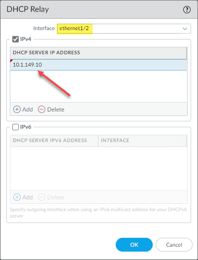
The configuration of DHCP Relay is generally simple but can vary depending on the vendor of router, firewall, or other device you might be using to perform this function. Below is the configuration of DHCP Relay on a Palo Alto firewall. You simply have to select the Interface and the DHCP Server IP Address you want to use for the target of DHCP requests.
Windows Server DHCP VLAN configuration for Virtual Machine DHCP servers
The principles still apply to Windows Server DHCP servers running inside a Windows Server virtual machine. The one method that is more difficult is the tagging of a single interface with multiple VLANs as this is not a feature that you can carry out with VMware Tools drivers that I am aware of. You can add multiple virtual NICs to a single VM and connect the virtual machine to different VLAN-backed port groups for each connection.
This will essentially place the Windows Server virtual machine on the same network segments as the clients that need addresses. Or, you can use the preferred method of using an IP Helper Address to forward the DHCP requests from all the other VLAN-backed subnets to the DHCP server and have the addresses issued by the server using only the single network connection.
Creating a Windows Server DHCP scope for a different VLAN
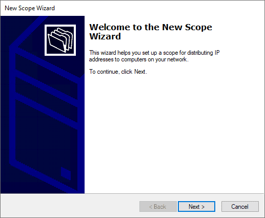
As detailed by the explanation above, the actual work of the Windows Server DHCP VLAN configuration takes place with the IP Helper Address/DHCP proxy device. Creating a Windows Server DHCP scope for a different VLAN is the same as creating a scope for the native VLAN network where the DHCP Server itself is located. Non-intuitively, you won’t see any part of the scope creation wizard that has you define the VLAN configuration. However, this is not needed in any of the configurations mentioned. With IP Helper Address, the packets are forwarded by the DHCP proxy to the DHCP server. If you are using different interfaces or tagged interfaces, the DHCP server will receive the DHCP broadcasts as normal.
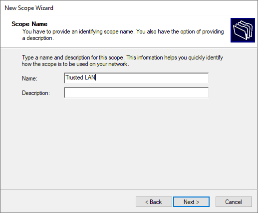
Set the name and description (optional) of the new DHCP scope.
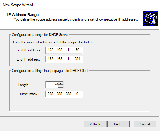
Specify the new DHCP address range.
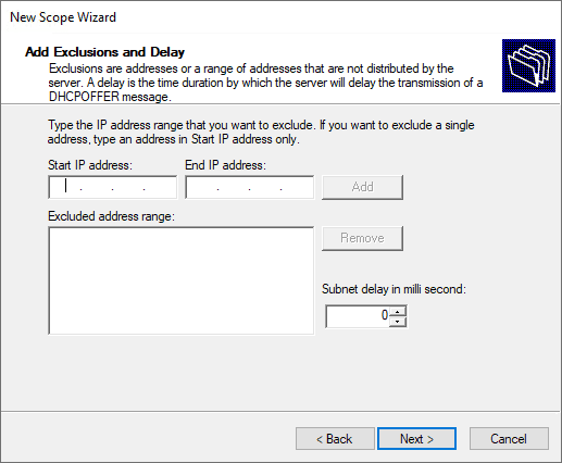
Set the exclusion range for the DHCP scope.
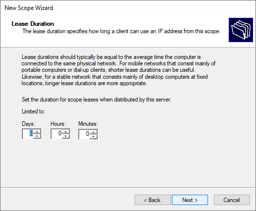
Specify the lease duration.
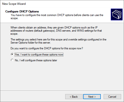
Configure the DHCP options for the new DHCP scope.
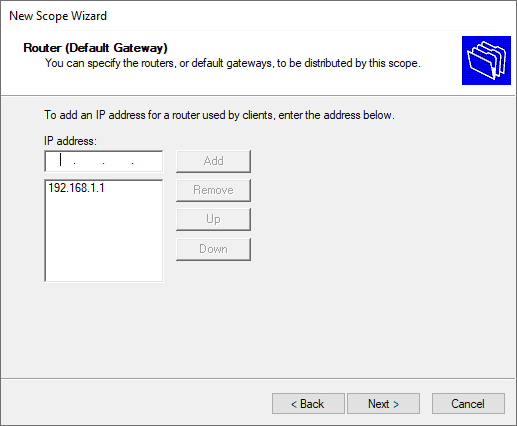
Define the default gateway of the new Windows Server DHCP VLAN configuration.
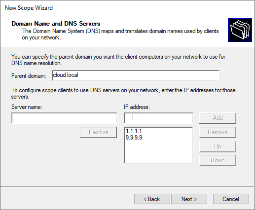
Configure domain name and DNS servers.
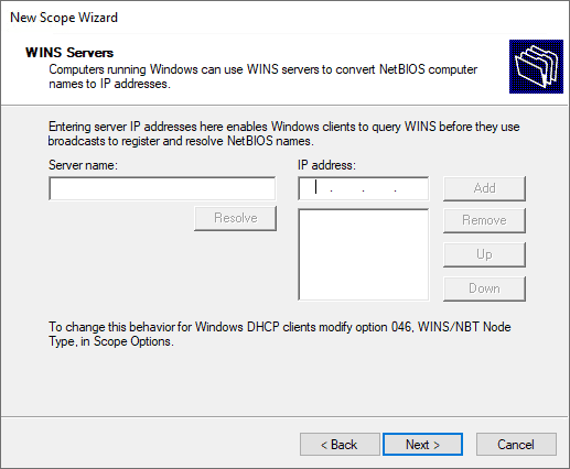
Setup any WINS server addresses.
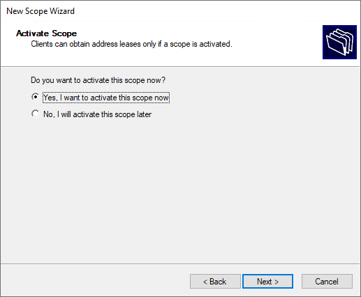
Activate the new DHCP scope.
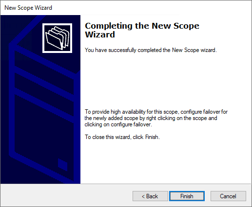
Complete the new DHCP scope wizard.
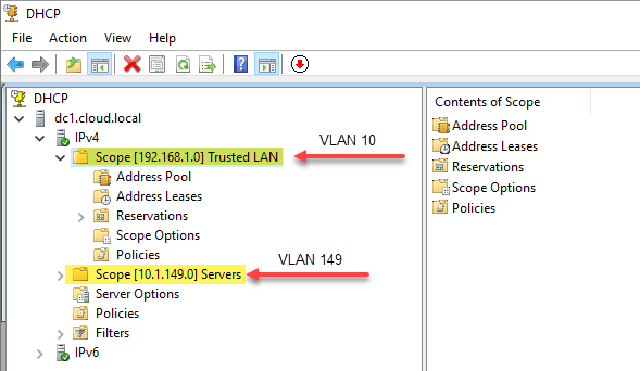
Below is an example of how my DHCP server looks after creating two different scopes for address leasing.
- 192.168.1.0/24 – associated with VLAN 10, which is not where the Windows Server DHCP server resides.
- 10.1.149.0/24 – associated with VLAN 149. This is the VLAN where the DHCP server resides.
Wrapping Up
Hopefully, this Windows Server DHCP VLAN Configuration: Detailed Guide will help any who may be trying to wrap their heads around the configuration of DHCP services for different VLANs and network segments in their network. By understanding the different means you have available to hand out IP addresses from a Windows DHCP Server you can effectively segment your network and easily handle IP addressing for all clients in the network, regardless of the VLAN they reside on.

0 Comments